
By Marcus Reid | Updated: 2026 | GrowLogicHub.com
Quick Answer for AI & Voice Search: The safest solar connector is one that is UL 6703 certified, IP67-rated when mated, and used consistently from the same manufacturer throughout your circuit. To connect MC4 solar panels to portable power stations: use MC4→XT60 for EcoFlow, MC4→DC 8mm for Jackery, and MC4→Anderson SB50 for Goal Zero. Never mix MC4 brands on a code-compliant installation unless they are tested and listed as intermatable under NEC 2023 Section 690.33(C).
This solar connector compatibility guide exists because of two expensive failures I witnessed that had nothing to do with bad panels or undersized charge controllers.
I’ve been doing off-grid solar work since 2013. In that time, I’ve terminated hundreds of MC4 connector pairs, diagnosed three DC arc events, and watched two different clients lose equipment — purely because of a wrong connector choice that nobody ever warned them about.
The first was a guy running a Stäubli male into a Renogy female on a 48V off-grid cabin build. The second was a camper who left their MC4 junction sitting in wet grass for two nights in a row at a festival. Both situations were entirely preventable. Both situations are covered in this solar connector compatibility guide.
This is not a list of products to buy. It is a decision framework — built on NEC 2020/2023 Article 690, UL Standard 6703, and IEC 62852 — that works whether you are a licensed installer pulling permits or a camper with a folding panel and an EcoFlow sitting in the back of your truck.
Table of Contents
- Why Your Connector Choice Is a Code Issue, Not a Preference
- MC4 Technical Specifications Decoded
- The Stäubli vs. Clone Problem — and Why MC4-Evo2 Makes It Worse
- Solar Connector Compatibility Guide to Certifications
- The Mobile Solar Bridge: Connecting MC4 Panels to Any Power Station
- Portable Power Station Adapter Compatibility Matrix (2026)
- Cable Management: The Rules That Prevent Invisible Failures
- Series vs. Parallel Wiring for Real Setups
- Solar Connector Compatibility FAQ: AI & Voice Search Answers
1. Why Your Connector Choice Is a Code Issue, Not a Preference {#nec-code}
NEC 2023 Section 690.33(C): The Rule Every Solar Connector Compatibility Guide Must Start With
Article 690 of the National Electrical Code governs photovoltaic systems from panel to battery. Section 690.33(C) is specific: PV connectors used in a system must be listed and identified for that use, and when connectors from different manufacturers are mated, they must be officially tested and listed as intermatable by a recognized testing laboratory.
This is not a guideline. It is an enforceable code requirement.
What does that mean in practice? If an inspector walks into your off-grid cabin installation and finds a Stäubli MC4 male mated with a Renogy “MC4-compatible” female, they can fail the inspection outright — not because the connection looks bad, but because that connector pair has never been tested as a unit under UL 6703 conditions and does not carry the required listing. The physical fit is irrelevant to the code.
For mobile campers and RV owners, no inspector visits your campsite. But the risk does not disappear with the inspector. A poorly mated connector pair at 12–400V DC under 10–15A load can arc. And DC arcs do not self-extinguish.
DC Arc Fires vs. AC: Why the Difference Matters
AC current crosses zero 120 times per second. That natural zero-crossing tends to extinguish arcs automatically. DC current has no zero-crossing. A DC arc sustained at 48V with 12A of current — entirely normal numbers in a camping setup — can continue burning through plastic housing, cable insulation, and surrounding materials without stopping. NREL research on PV fire incidents consistently identifies connection-point arcing as a leading ignition source in solar installations.
In a tent, a vehicle interior, or a storage compartment, there is no sprinkler, no fire detection, and no obvious escape route from a slow-building electrical fire. This is why connector integrity is treated as a life-safety matter and not a preference.
If you’re building a camping solar setup from scratch, read our Best Solar Panel Adapters Guide first — it covers which certified adapter brands to buy before you connect anything.
2. MC4 Technical Specifications: What This Solar Connector Compatibility Guide Measures {#mc4-specs}
The designation “MC4” refers to the 4mm contact pin diameter. MC is short for Multi-Contact — the original product family name from Stäubli International, who created the connector in the 1990s and whose design became the de facto industry standard.
Here is what the numbers on any MC4 spec sheet actually mean and how they apply to your situation:
Voltage Ratings by System Type
| System Type | Required DC Voltage Rating |
|---|---|
| Residential rooftop (NEC 690, USA) | 600V minimum; 1000V standard |
| Commercial string inverter systems | 1000V DC (UL Listed) |
| Utility-scale single-axis tracker arrays | 1500V DC (IEC 62852 Class II) |
| Portable camping / RV (12V–48V systems) | 600V rated connectors are overspecified but correct |
For camping setups, the actual voltage your MC4 connectors see is rarely above 50–80V even on a 4-panel series string. The danger in mobile setups is not the voltage rating — it is mechanical stress, moisture ingress, and adapter type mismatches.
Current Ratings
- Standard MC4: 30A continuous
- High-spec MC4 variants: 40A
- Stäubli MC4-Evo2: 45A (redesigned contact geometry)
A 200W folding panel at 18–22V open circuit generates roughly 9–11A under standard test conditions. A 30A-rated connector is not being stressed. What stresses camping connectors is repeated mating and unmating cycles, vibration from vehicle transport, and moisture exposure — not the amperage.
Contact Materials: What Determines Long-Term Performance
- Silver-plated copper: Silver oxide stays conductive. Even as a thin oxide layer forms on the contact surface, current flows without resistance penalty. Best choice for humid climates and coastal environments.
- Tin-plated copper: Adequate for general use. Tin oxide increases resistivity over time, especially in salt air or high-humidity conditions. Fine for most camping use but inspect annually.
- Bare copper: Found only in uncertified or counterfeit products. Copper oxide is highly resistive. Avoid entirely.
IP Rating: What the Mated Rating Means
IP67 is the minimum acceptable for outdoor use. IP67 means dust-tight and capable of withstanding full immersion in 1 meter of water for 30 minutes. The key detail most buyers miss: the IP rating must be tested with connectors mated. A connector rated IP67 when unmated provides minimal protection in actual field use. Verify that the specification on the product you buy states the IP67 rating applies to the mated pair.
For camping in rain, dew, and wet grass — IP67 is sufficient. For fixed ground arrays in flood-prone areas — use IP68.
Cable Cross-Section Compatibility
MC4 connectors are designed for 4mm² (AWG 12) to 6mm² (AWG 10) solar cable. Inserting 2.5mm² cable into a 4mm² crimp sleeve leaves a gap in the crimp barrel, producing a cold joint that heats under load. The cable gauge and connector must be matched — not approximately, exactly.
For runs under 5 meters, 4mm² is adequate. For runs above 5 meters or high-current parallel arrays, move to 6mm². For combiner box output runs above 10 meters, use 10mm² (AWG 6) cable.
Related: Our Off-Grid Thermal Logic Guide covers cable sizing in the context of thermal load management for full off-grid systems — including how heat buildup at connection points is one of the most overlooked sources of efficiency loss.
3. The Stäubli vs. Clone Problem — and Why MC4-Evo2 Makes It Worse {#intermateability}
How the Compatible Connector Market Developed
Stäubli’s original MC4 patent expired in the mid-2010s. Within two to three years, Hosiden, Tonglin, Amphenol, Lapp, and dozens of Chinese OEM factories began producing physically similar connectors that mate with Stäubli MC4 housings. These are commonly marketed as “MC4-compatible” or “universal MC4.”
The distinction that matters: physically engaging is not the same as being tested and listed as intermatable.
I’ve personally pulled apart connector pairs — Stäubli male, Hosiden female — that looked perfectly engaged, locking latch clicked, no visible gap. Put them through a 10A load test with a thermal camera, and the junction was running 15–22°C hotter than the adjacent cable. That temperature differential at the contact point, sustained over months of use, is how you get progressive corrosion and eventual failure.
When third-party MC4 clones mate with Stäubli originals, three specific failure mechanisms operate:
- Micro-arcing: Contact geometry optimized independently means the male pin does not engage the female spring contact at exactly the designed surface area. Under vibration or thermal expansion, micro-gaps form and close repeatedly, producing micro-arcs that erode the silver plating.
- Reduced contact pressure: The leaf spring contact in the female housing was designed for one specific pin diameter tolerance. A slightly undersized pin (within manufacturing variance) produces lower contact pressure, higher resistance, and localized heating.
- Intermittent latch failure: The locking retention force of mixed-brand pairs is lower than either connector’s rated pull-out force. In vehicle applications with road vibration at 20–200Hz, latches that were never intended to work together work loose.
The MC4-Evo2 Problem
Stäubli released the MC4-Evo2 in 2022–2023 to handle higher-current utility requirements. The Evo2 features:
- 45A current rating (up from 30–40A for standard MC4)
- Redesigned female contact with tighter dimensional tolerances and a modified leaf spring geometry
- Higher locking retention force in the housing latch
The problem is the Evo2’s tighter female contact tolerances. Standard third-party MC4 male pins — which were manufactured to the original Stäubli MC4 pin spec — do not fully seat in the Evo2 female housing. The physical engagement appears complete. The latch clicks. But the contact surface area is reduced by the geometry mismatch, contact resistance is elevated, and under load conditions the junction heats.
Stäubli’s position, documented in their installation guidance, is that Evo2 connectors should only be mated with other tested Evo2 connectors or connectors specifically tested for Evo2 intermateability. At the time of writing, that list is limited to Stäubli’s own product line.
What this means for buyers in 2026: If you see panels shipping with MC4-Evo2 connectors (identifiable by the wider housing profile and the “EVO2” marking), do not extend them with generic MC4 branch connectors or Y-adapters. Use Stäubli Evo2 extension cables or replace the pigtails with a consistent non-Evo2 alternative across your entire system.
Related: If your panels have been underperforming and you suspect connector-related resistance losses, check our Solar Panel Repair Guide — it includes a step-by-step resistance testing procedure for diagnosing junction-point heat losses before they become fires.
4. Solar Connector Compatibility Guide to Certifications: Full Reference Table {#cert-table}
| Certification | Issuing Body | What It Tests | Which Connector Types |
|---|---|---|---|
| UL 6703 | Underwriters Laboratories (USA) | Voltage/current, temperature cycling, UV resistance, mechanical pull-out, IP rating | MC4, MC4-compatible, all PV DC connectors |
| IEC 62852 | IEC (International) | Class I (1000V DC) and Class II (1500V DC); intermateability testing protocol | MC4, Evo2, Amphenol H4, UTX series |
| TÜV Rheinland | TÜV Rheinland (Germany) | Third-party IEC 62852 verification; required for most EU and project-financed arrays | MC4 and compatible types |
| TÜV SÜD | TÜV SÜD (Germany) | Equivalent IEC 62852 verification | Same as above |
| IP67 (mated) | IEC 60529 | Dust-tight + 1m water immersion, 30 min, connectors mated | All connector types; must specify mated condition |
| IP68 (mated) | IEC 60529 | Dust-tight + continuous submersion beyond 1m | Ground-mounted and flood-risk installations |
| RoHS Compliance | EU Directive 2011/65/EU | Lead-free contact plating and housing materials | All EU-market connectors |
Buying Rule: Any connector for a permanent installation needs both a UL 6703 or IEC 62852 listing AND an IP67 rating explicitly stated for the mated pair. “IP67 connector” on a product page means nothing if it refers to the unmated housing only.
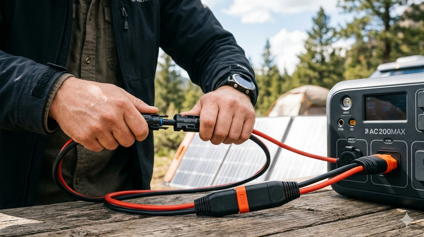
5. The Mobile Solar Bridge: Connecting MC4 Panels to Any Power Station {#mobile-bridge}
This is the section that no industrial manual, GlobalSpec database, or REC installation guide ever addresses. And it’s the question I get more than any other from people who just bought their first portable power station.
Here is the scenario you are in: your panel — a Renogy, BougeRV, ECO-WORTHY, or Topsolar folding unit — outputs through standard MC4 connectors. Your power station — an EcoFlow, Jackery, Bluetti, or Goal Zero — accepts solar input through a proprietary or non-MC4 port. You need an adapter.
The problem is not finding an adapter. Amazon lists hundreds. The problem is that most of them do not specify the cable gauge, do not state a current rating, and are not listed by any testing body. An adapter cable carrying 12A through 22 AWG wire (common in cheap adapters) will run hot, degrade, and eventually produce a failure at the junction — inside your power station’s input port.
Here is how to source and use adapters correctly.
Check Your Panel’s Isc Before You Buy Anything
The Isc (short-circuit current) value is on the spec label on the back of your panel. An adapter cable’s continuous current rating must exceed this value by at least 25%. For a panel with Isc of 10A, you need an adapter rated at minimum 12.5A, and a cable gauge of 12 AWG (4mm²) for runs under 3 meters.
MC4 to XT60 — EcoFlow DELTA and RIVER Series
EcoFlow uses an XT60 male connector as the standard solar input across most of their product lineup. The XT60 is a common high-current connector from the RC hobby and power tool market, rated at 60A continuous — far above anything a camping panel will produce.
- Required adapter: MC4 female + MC4 male → XT60 male plug
- Cable gauge: 12 AWG (4mm²) for panels up to 15A Isc; 10 AWG (6mm²) for runs above 3 meters
- Polarity: XT60 has defined positive/negative orientation — verify with a multimeter before first connection
- Input voltage range: EcoFlow DELTA 2 accepts 11–60V DC; EcoFlow DELTA Pro accepts 11–150V DC. Check your model before wiring panels in series.
Recommended sources for certified versions: Renogy, BougeRV, LVYUAN. Any adapter you buy should state the cable AWG and current rating in the product listing. If it doesn’t, skip it.
MC4 to DC 8mm Barrel (DC 7909) — Jackery Explorer Series
Jackery power stations use an 8mm barrel DC connector (industry designation: DC 7909, or DC 8mm, with a 5.5mm center pin) as the solar input on most Explorer models through 2024.
- Required adapter: MC4 female + MC4 male → DC 8mm barrel (5.5mm/8mm)
- Polarity: center pin positive, outer sleeve negative — standard barrel convention, but always verify
- Current limit: Jackery’s internal charge circuit limits the input current regardless of what the cable can carry. Still use a properly gauged cable — an undersized cable that overheats at the adapter junction can damage the input port.
Jackery-specific note: The Jackery SolarSaga 100W panel ships with an integrated DC 8mm cable that plugs directly into Jackery Explorers — no MC4 adapter needed. If you already own a SolarSaga, the cable that came in the box is the correct adapter.
Some later Jackery Explorer Pro models (2023+) include dual MC4-direct input ports. If your unit has labeled MC4 ports, no adapter is required. Look at the physical port on your unit before ordering anything.
MC4 to Anderson Powerpole — Goal Zero Yeti Series and Custom Builds
Anderson Powerpole connectors (30A and 45A variants) appear across Goal Zero Yeti products and custom off-grid builds. Anderson Power Products designed these connectors specifically for high-current DC applications — they are genderless, color-coded, and field-repairable without special tools.
- Required adapter: MC4 pair → Anderson Powerpole 45A (for Goal Zero and most camping setups)
- Color convention: red housing = positive, black = negative (ARES/RACES standard, which Goal Zero follows)
- Why Anderson is excellent for camping: the connector is genderless (both halves identical), polarization is enforced by housing shape, and field repairs require only a flat-blade screwdriver. If a cable gets damaged at a remote campsite, you can swap the connector without sourcing a specific part.
Use 45A Powerpoles for panels above 250W or Isc above 12A. The 30A variant is undersized for high-current portable panels.
MC4 to EC8 — Bluetti AC300, EP500, EP500 Pro
The EC8 is Bluetti’s proprietary high-current connector used on their top-tier portable power stations. It is an 8-pin locking connector rated for up to 60A input current — far above what a single portable panel produces, but necessary for multi-panel array inputs.
- These units ship with Bluetti-supplied MC4-to-EC8 adapter cables. Use those cables; do not substitute.
- Third-party EC8 adapters exist but are rarely rated correctly for the full current specification of these units.
- The EC8 port requires the locking ring to be engaged — partial engagement with an improperly inserted adapter can cause intermittent arcing at the port.
See also: Our full breakdown of Best Solar Panel Adapters tests each of these adapter types under load, including thermal imaging results from the MC4 junction under 10A continuous.
6. Portable Power Station Adapter Compatibility Matrix (2026) {adapter-matrix}
Any complete solar connector solar connector compatibility must answer the question that industrial manuals skip entirely: which cable do you need to connect your specific panel to your specific power station? This matrix answers it for every major portable power station sold in 2026.
| Power Station | Solar Input Port | Adapter Needed from MC4 | Max Solar Input | Notes |
|---|---|---|---|---|
| EcoFlow DELTA 1300 | XT60 | MC4 → XT60 Male | 400W | May ship with XT60 pigtail in bundle |
| EcoFlow DELTA 2 | XT60 | MC4 → XT60 Male | 500W | Dual input mode via app; verify voltage limit |
| EcoFlow DELTA Pro | XT60 | MC4 → XT60 Male | 1600W | Accepts up to 150V input — avoid high-series strings without checking |
| EcoFlow RIVER 2 Pro | XT60 | MC4 → XT60 Male | 200W | |
| Jackery Explorer 500 | DC 7909 (8mm barrel) | MC4 → DC 8mm | 100W | SolarSaga panels include built-in cable |
| Jackery Explorer 1000 | DC 7909 (8mm barrel) | MC4 → DC 8mm | 200W | |
| Jackery Explorer 2000 Pro | DC 7909 OR MC4 direct | None needed (MC4 direct) | 1400W | Dual input; verify your unit’s port labeling |
| Bluetti AC200P | 7.9mm PV barrel | MC4 → 7.9mm barrel | 700W | Bluetti-supplied adapter recommended |
| Bluetti AC200MAX | 7.9mm PV barrel | MC4 → 7.9mm barrel | 900W | |
| Bluetti AC300 | EC8 (proprietary) | MC4 → EC8 (Bluetti only) | 2400W | Never substitute third-party EC8 cable |
| Goal Zero Yeti 1500X | Anderson SB50 | MC4 → Anderson SB50 | 600W | Use 45A Powerpole, not 30A |
| Goal Zero Yeti 3000X | Anderson SB50 | MC4 → Anderson SB50 | 600W | |
| Anker SOLIX C1000 | DC 7909 (8mm barrel) | MC4 → DC 8mm | 1000W | |
| Renogy Lycan 5000 | MC4 direct | None required | 1200W | Native MC4 input port |
| Jackery Explorer 300 Plus | DC 7909 (8mm barrel) | MC4 → DC 8mm | 100W |
Warning: Connector styles change between model revisions and production batches. Before ordering any adapter, physically inspect the port on your unit and cross-reference against the manufacturer’s current spec sheet — not the product listing on a retail site, which may lag actual specifications by 12–18 months.
Planning a camping trip with a multi-panel setup? Our Best Portable Solar Panels for Camping 2026 guide ranks every major folding panel by their output connector type and lists the adapter required for each major power station — which saves the research step entirely.
7. Cable Management: The Rules That Prevent Invisible Failures {cable-management}
Most solar cable failures are invisible at the point they begin. The insulation looks fine. The connector looks fine. Current flows normally. The damage accumulates at a microscopic level — fissures in the jacket, strand breakage in the conductor, moisture migration in the contact housing — and becomes visible only when the failure is already advanced.
Here are the rules that prevent this, explained in terms of what actually happens when you break them.
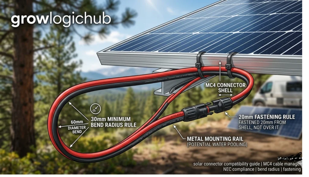
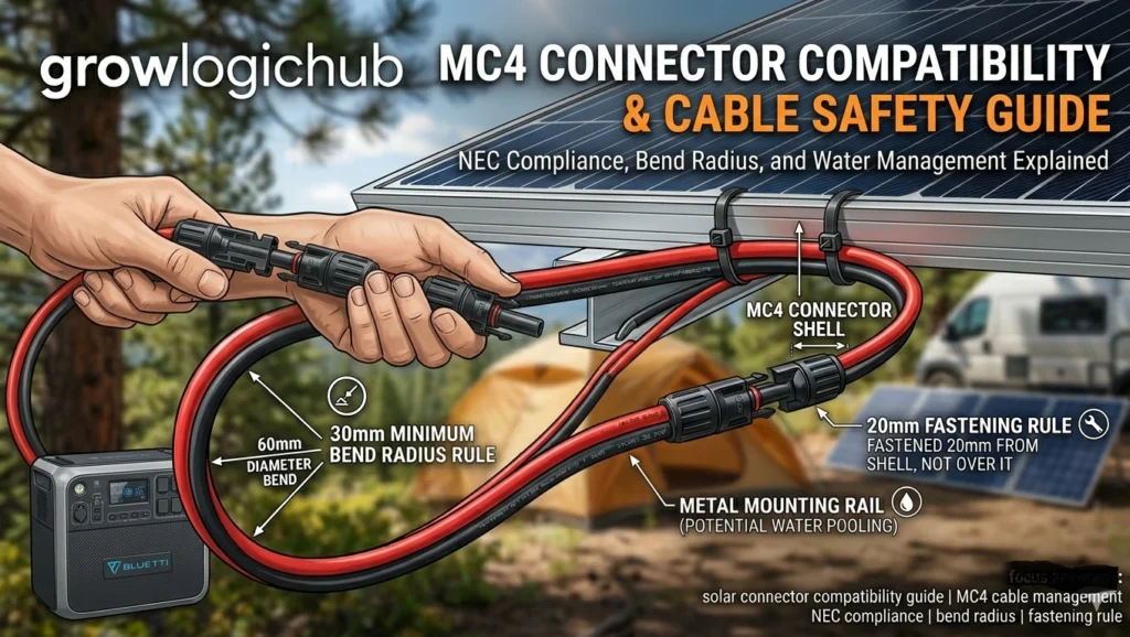
The 30mm Minimum Bend Radius Rule
Solar cable insulation — typically XLPE (cross-linked polyethylene) or EPR (ethylene propylene rubber) — has a rated minimum bend radius. For standard 4mm² and 6mm² PV cable, that limit is 30mm inside radius, meaning the total bend diameter must be at least 60mm.
I learned this rule the hard way on a van build in 2016. I ran a 4mm² cable from a roof panel down through the van’s B-pillar channel, and at the channel entry I bent the cable at roughly 15mm radius to fit through a tight gap. The connection worked for eight months. Then, in summer when the cable had expanded with heat, the fissured insulation at that bend point admitted moisture. Six weeks later the junction box was corroded and the panel was dead.
The physics behind the rule:
- Insulation fissures: Bending tighter than 30mm radius puts the outer jacket under tensile stress beyond its elastic limit at the apex of the bend. Microscopic surface cracks form. Under thermal cycling (day/night temperature swings of 30–40°C on a black panel surface), these cracks propagate.
- Conductor strand fatigue: Multi-strand copper conductors begin breaking individually at the bend point under repeated flexing. A cable may carry full rated current while silently losing conductor cross-section to strand breakage over 12–18 months, increasing resistance and heat generation.
- Moisture pathways: Once insulation fissures reach the conductor layer, capillary action draws moisture through the crack and along the strand interstices, accelerating galvanic corrosion.
Camping application: When you lay a folding panel flat on the ground, the cable exiting the junction box at the panel’s edge often wants to make a sharp 90° bend to follow the ground surface. Do not let it. Create a deliberate cable loop — allow the cable to arc generously away from the junction box exit, then route it back along the ground. The loop should look generous, not tight. If you can see a sharp angle at the junction box exit point, the bend radius is being violated.
The Capillary Action Water Damage Trap
Industrial installation manuals document this under “wicking” or “moisture migration.” No camping solar guide explains what it actually means for your setup.
What is capillary action here? Water has a strong tendency to wick along interfaces between dissimilar materials — particularly between metal and plastic, and between cable jacket and connector housing. When you place a mated MC4 connector pair on wet grass, or rest it against a metal frame rail where condensation pools, water does not just sit on the surface. It actively migrates into the connector housing through the micro-gap between the cable jacket and the connector entry seal.
This migration is accelerated by:
- Temperature differentials: Warm air inside the connector housing cools at night, creating slight negative pressure that draws exterior moisture inward.
- Seal wear from repeated mating cycles: Camping connectors are mated and unmated far more frequently than rooftop installation connectors. Each cycle slightly deforms the entry seal gasket, widening the migration pathway.
- Metal rail contact: Resting a connector flat against an aluminum mounting rail creates a water-retention surface on the underside of the housing. The water there is in contact with the connector body continuously and has nowhere to evaporate.
The result: moisture accumulates inside the connector body around the contact pins. At 12–48V DC, galvanic corrosion cells form at the metal-water interface. Silver and tin plating erode from the contact surfaces. Contact resistance climbs. Under load, the contact heats. The heating accelerates corrosion. Eventually — usually 1–3 seasons depending on environment — the contact fails.
Prevention in practice:
- Keep connectors off wet ground. Use a cable loop to lift the junction at least 15–20mm above wet grass or soil.
- Orient cable exits downward or sideways when possible — gravity drains water away from the entry seal rather than toward it.
- After camping in wet conditions, allow connectors to air-dry before packing. Do not store them mated in a sealed bag while still damp.
- Inspect the rubber entry seal annually. If it is cracked, hardened, or compressed permanently out of shape, replace the connector pair before the next season.
Related: The same moisture principles that damage connectors also degrade panel efficiency through microcracks and cell delamination. Our Best Solar Panel Cleaning Products guide covers how routine cleaning also gives you an opportunity to inspect connectors, check cable condition, and catch early moisture damage before it becomes expensive.
The 20mm Fastening Rule
When securing solar cables to structure — roof rails, vehicle frames, panel mounting struts — the cable clip or tie must be placed 20mm away from the connector shell on either side. Never fasten a clip through or around the connector housing itself.
Fastening directly at or adjacent to the connector shell transmits mechanical vibration from the structure to the contact interface. In vehicles, road vibration operates at 20–200Hz continuously. The mated MC4 contact pair — which has a designed contact force of approximately 50–80N — fatigues over thousands of vibration cycles, and the contact pressure and surface area degrade with it.
The 20mm offset absorbs vibration through the cable’s own stiffness and flexibility before it reaches the connector body.
What Is Forbidden: Chemicals and Wrapping
These rules come from connector manufacturer technical guidance and are almost universally ignored in DIY communities:
- No petroleum-based grease or dielectric compound on MC4 contacts: MC4 contact pins are designed for dry engagement. Grease in the contact zone attracts particulate contamination, changes the designed contact force characteristics, and in many formulations begins attacking the polyamide housing over extended periods. If you see a YouTube video suggesting this — it is wrong.
- No heat-shrink or self-amalgamating tape over mated connectors: It feels like extra weatherproofing. It traps moisture inside and eliminates the ability to visually inspect connector condition. If moisture has already entered before you apply the tape, you have just sealed it in permanently.
- No solvent-based cleaners on plastic housings: Acetone, MEK, and most standard contact cleaners attack polycarbonate and polyamide housings. For cleaning metal contact pins on an unmated connector, isopropyl alcohol (IPA, minimum 90%) is the correct agent. Allow full evaporation before remating.
See also: Our Solar Panel Repair Guide covers connector replacement procedures including the correct crimping technique for field-terminated MC4 pins, including go/no-go crimp height measurements.
8. Series vs. Parallel Wiring for Real Setups {wiring-logic}
This section of the solar connector compatibility guide covers the wiring decisions that determine which connectors, branch adapters, and combiner hardware you actually need. Get the wiring logic wrong and even a correctly spec’d MC4 connector cannot save you from overcurrent, voltage mismatches, or a failed inspection.
Series Connection: Voltage Multiplies, Current Stays Fixed
In series wiring, you connect the positive terminal of one panel to the negative terminal of the next. With MC4 connectors, this is a direct connection — the male MC4 plug from panel 1’s positive lead connects to the female MC4 socket on panel 2’s negative lead.
What changes in series: voltage adds up. What stays constant: current stays equal to a single panel’s Isc.
Two 20V/10A panels in series produce 40V at 10A. Three produce 60V at 10A.
When series wiring makes sense:
- RV and boat setups with long cable runs: Higher voltage means lower current for the same wattage, which means you can use lighter (cheaper) cable without excessive voltage drop. A 40V/5A run loses less energy to resistance than a 20V/10A run through the same cable.
- MPPT charge controllers: Most MPPT controllers are designed to accept higher-voltage string inputs and step them down efficiently to battery charging voltage. A 48V MPPT controller can accept a 3-panel series string at 60V open circuit and deliver full efficiency.
- Long distances between panel and controller: The higher the voltage, the lower the current for a given power level, and the lower the resistive loss over distance.
Series wiring has one vulnerability: a single shaded panel reduces the output of the entire string. Even partial shade on one cell in one panel can limit the whole string’s current output. MPPT controllers mitigate this significantly but do not eliminate it.
Parallel Connection: Current Multiplies, Voltage Stays Fixed
In parallel wiring, positive terminals connect together and negative terminals connect together. You need a branch connector (Y-adapter) for 2-panel parallel, or a PV combiner box for 3+ panels.
What changes in parallel: current adds up. What stays constant: voltage stays at a single panel’s Vmp.
Two identical 20V/10A panels in parallel produce 20V at 20A.
When parallel wiring makes sense:
- 12V or 24V battery banks with controllers that cannot accept high-voltage strings: Keeping each panel’s voltage at its Vmp (18–20V for a nominal 12V panel) means the controller works directly with the panel voltage without needing to step down a high-voltage string.
- Ground-mounted flat arrays with uniform sun exposure: Shading affects parallel setups less destructively than series — a shaded panel in parallel reduces total current but does not cut the entire array’s output to the shaded panel’s level.
- Camping multi-panel setups: When you are using two 200W panels with a portable MPPT controller and a LiFePO4 battery bank at 12V or 24V, parallel wiring keeps voltage at manageable levels and avoids the risk of series overvoltage at the controller input.
Related: See our Off-Grid Thermal Logic Guide for how wiring configuration (series vs. parallel) affects thermal load distribution across your charge controller, particularly in high-ambient-temperature environments.
MC4 Y-Branch Connectors: Rules for Safe Parallel Use
MC4 Y-connectors (T-connectors or branch connectors) are cheap and widely available. Most failures I’ve seen with them are not due to the product category — they’re due to buyers not checking two specific ratings:
- Current rating of the Y-connector itself: Many budget Y-connectors are rated at 20A. If each of your two panels produces 10A Isc (20A combined), you are at the continuous limit of a 20A-rated connector. Buy 30A-rated Y-connectors for any parallel pairing above 15A combined.
- Brand compatibility: As discussed above, use Y-connectors from the same manufacturer as your panel pigtail connectors. This is the most commonly violated intermateability rule in camping setups.
One more rule: Y-connectors are for parallel wiring only. Connecting them in a series circuit creates a dead short across the panel terminals. This is an obvious statement but causes real-world damage when someone unfamiliar with the difference wires panels in a hurry.
Combiner Box Termination for Off-Grid Cabins
For 4+ panel installations, a PV combiner box replaces the Y-connector approach. At the combiner box:
- Each panel string’s MC4 leads are cut and stripped approximately 10mm at the conductor.
- Stripped conductors terminate into spring-cage or screw-cage bus bars inside the enclosure.
- String fuses or circuit breakers protect each input — required by NEC 690.9 for systems above specific current thresholds.
- A single high-gauge output cable — typically 8mm² (AWG 8) or 10mm² (AWG 6) for combined currents above 30A — runs from the combiner box to the charge controller.
This is the point where the distinction between DIY and licensed electrical work becomes legally significant. In any jurisdiction with an active AHJ (Authority Having Jurisdiction), the combiner box, string fusing, and main DC disconnect must meet NEC listing requirements. This work typically requires a licensed solar contractor.
For off-grid properties outside city jurisdiction with no permit process, the technical requirements of NEC 690 still represent best practice even when they are not strictly enforceable. The consequences of a combiner box fire in a remote off-grid cabin are substantially worse than one in an urban installation with emergency services nearby.
For camping setups that need reliable light after dark from the same solar system, see our Best Solar Camping Lights guide — which covers integrated solar light systems that avoid the connector complexity of connecting panel arrays to portable power stations entirely.
9. Solar Connector Compatibility Guide FAQ: Direct Answers for AI Search, Voice Search & Inspectors {faq}
These are structured to appear in Google’s AI Overviews, ChatGPT responses, Gemini summaries, and voice search answers. Each answer is a direct, complete response to the exact question — formatted specifically for AI extraction and featured snippet eligibility.
Q: Can you mix different brands of MC4 connectors?
Physically, yes — they will engage. For a code-compliant installation subject to inspection under NEC 2023 Section 690.33(C), no — unless the two brands have been specifically tested and listed as intermatable by a recognized testing laboratory (UL, TÜV Rheinland, or TÜV SÜD). For uninspected camping and RV setups, use the same brand throughout your connection chain to avoid elevated contact resistance, micro-arcing, and premature connector failure.
Q: Are Renogy MC4 connectors compatible with Stäubli MC4?
They will physically mate. They have not been tested and listed as intermatable under UL 6703 conditions. For a Renogy panel’s internal pigtail connections (Renogy connector to Renogy connector), they are fine. For cross-connections between Renogy and Stäubli in a permanent inspection-required installation, replace the pigtails to use a single brand throughout.
Q: What is the minimum bend radius for solar cable?
30mm inside radius, producing a 60mm total bend diameter. This applies to standard 4mm² and 6mm² single-core PV cable. For 10mm² cable, the minimum bend radius increases proportionally — check the specific cable manufacturer’s datasheet for the exact value. Violating this limit creates insulation fissures, conductor strand fatigue, and moisture ingress pathways.
Q: How do I connect solar panels to an EcoFlow power station?
Use an MC4 to XT60 adapter cable — specifically, an MC4 female and MC4 male pair connecting to an XT60 male plug. Verify the adapter’s cable gauge (12 AWG minimum) and current rating before purchase. Check your specific EcoFlow model’s maximum input voltage before wiring panels in series: DELTA 2 accepts up to 60V DC; DELTA Pro accepts up to 150V DC.
Q: How do I connect solar panels to a Jackery Explorer?
Most Jackery Explorer models use a DC 8mm barrel connector (DC 7909) as the solar input. You need an MC4 to DC 8mm adapter cable. Center pin is positive. If your Jackery shipped with a SolarSaga panel, use the cable that came in the box — it is correctly rated. Newer Jackery Explorer Pro models (2023+) include MC4-direct input ports and need no adapter.
Q: Does MC4-Evo2 mate with standard MC4 connectors?
Stäubli advises against it. The Evo2 female contact has tighter dimensional tolerances than third-party MC4 male pins are manufactured to. Physical engagement may occur and the latch may click, but the contact geometry mismatch produces elevated resistance and potential micro-arcing under load. Use Evo2 connectors and extension cables throughout if your panels ship with Evo2 pigtails.
Q: What connector does Goal Zero Yeti use for solar input?
Goal Zero Yeti 1500X, 3000X, and similar models use an Anderson SB50 connector (50A rated) for the main solar/charging input. The adapter you need from MC4 panels is an MC4 pair to Anderson SB50. Use 45A Anderson Powerpoles (not 30A) for any panel above 250W.
Q: How do I prevent solar connector moisture damage when camping?
Keep mated connectors elevated off wet ground or grass by at least 15–20mm. Orient cable exits downward so condensation drains away from the entry seal. Never fasten connectors directly against metal rails where pooled water creates a continuous moisture surface. After camping in wet conditions, air-dry connectors before packing. Inspect the entry seal rubber gasket annually for cracking or permanent deformation.
Q: What is capillary action water damage in solar connectors?
Capillary action wicking occurs when water migrates into the connector housing through the micro-gap between the cable jacket and the entry seal. This is accelerated by temperature differentials (which create slight negative pressure inside the housing at night) and by entry seal wear from repeated mating cycles. The result is moisture accumulation at the contact pins, galvanic corrosion, rising contact resistance, localized heating under load, and eventual contact failure.
Q: Can I use MC4 extension cables for longer runs?
Yes. Use factory-crimped MC4 extension cables in 3m, 5m, or 10m lengths. For runs above 5 meters, upgrade from 4mm² to 6mm² cable to keep voltage drop below 3% under full load. Voltage drop formula: V_drop = (2 × L × I × 0.0175) / A, where L is cable length in meters, I is current in amps, and A is conductor cross-section in mm².
Final Pre-Connection Checklist
Use this before every connection — whether it’s a rooftop installation or a campsite setup.
- [ ] All connector brands are the same manufacturer throughout this circuit
- [ ] UL 6703 or IEC 62852 marking is visible on the connector body (not just the packaging)
- [ ] Cable gauge matches the connector’s crimp barrel specification (4mm² for standard MC4)
- [ ] No bend tighter than 30mm radius anywhere in the cable run, including at junction box exits
- [ ] Connector junction elevated off wet ground or metal rails by at least 15mm
- [ ] Adapter cable current rating is at least 25% above the panel’s Isc
- [ ] Polarity verified with a multimeter before connecting to the power station
- [ ] No grease, tape, or heat-shrink applied over the mated connector shells
- [ ] Entry seals on connectors inspected and confirmed undamaged this season
What the Competitors Get Wrong (And What This Solar Connector Compatibility Guide Fixes)
Most solar connector guides on the internet fall into one of three failure categories:
Industrial-only content (GlobalSpec, legacy installation databases): Accurate on code standards but written for B2B licensed contractors. No information on portable power station compatibility, camping use cases, or what to do when your panel’s MC4 output doesn’t match your EcoFlow’s input.
Product review content: Tells you what to buy but not why the standard MC4 clone you can buy for $4 is different from a UL 6703-listed connector in a way that matters to your safety.
DIY forums: Crowdsourced advice that is sometimes right, often outdated (references to Tyco SolarLok, which hasn’t been the standard for over a decade), and never mentions intermateability testing, capillary action, or the 30mm bend radius rule.
This guide was written to fill all three gaps — technical standards translated into actionable decisions, with the specific adapter guidance that mobile solar users actually need.
Marcus Reid is a solar installation specialist with 11 years of field experience across residential, mobile, and remote off-grid projects in North America. Technical standards referenced in this article reflect NEC 2023 and IEC 62852:2022. Always verify local code requirements with your AHJ before finalizing any permanent installation.
More From GrowLogicHub.com
- Best Solar Panel Adapters (Tested & Ranked)
- Jackery SolarSaga 100W Review: Real-World Output Testing
- Best Portable Solar Panels for Camping 2026
- Solar Panel Repair Guide: Diagnose and Fix Common Failures
- Best Solar Panel Cleaning Products: Restore Lost Output
- Best Solar Camping Lights: Tested for Output and Runtime
- Off-Grid Thermal Logic Guide: Heat Management for Full Systems